
How to Choose the Right RF Component for Your System
Precision Engineering Guide: Selecting high-performance RF microwave power splitters, directional couplers, attenuators, cavity filters, and isolators up to 70 GHz.
About Chengdu Leader Microwave Technology Co., Ltd.
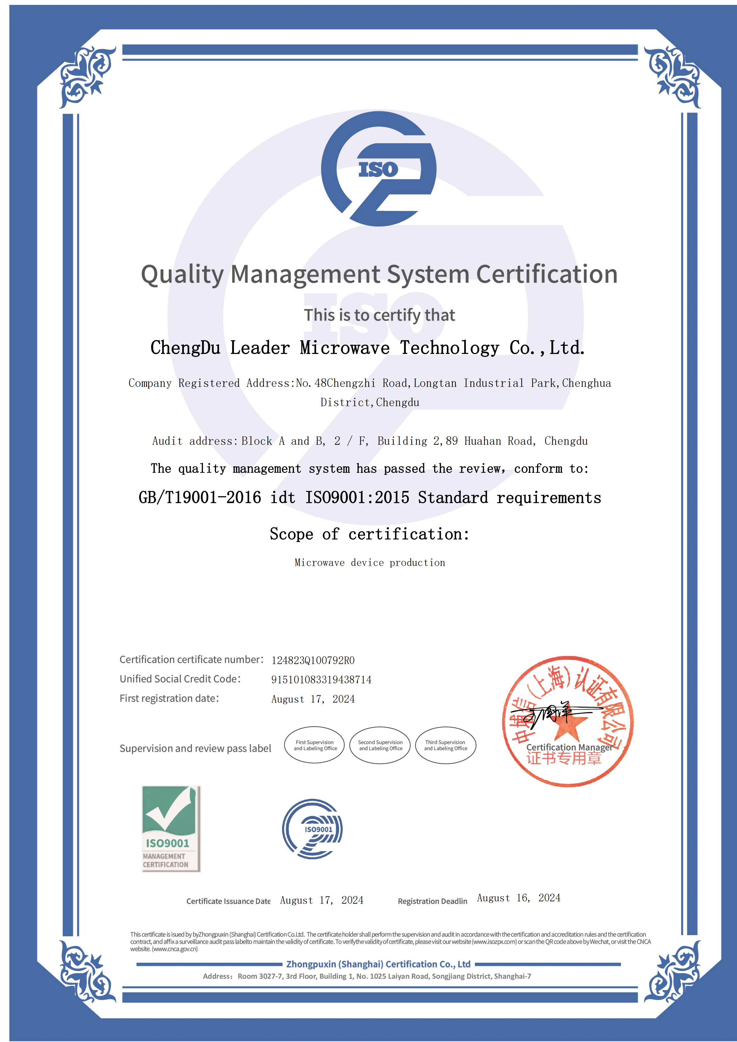
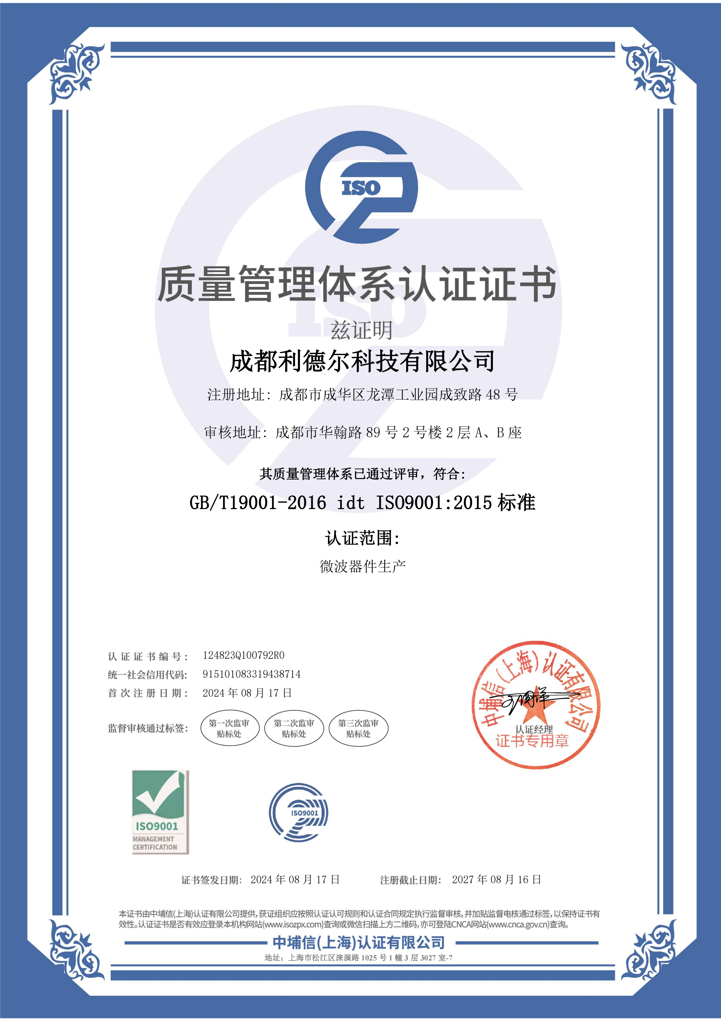
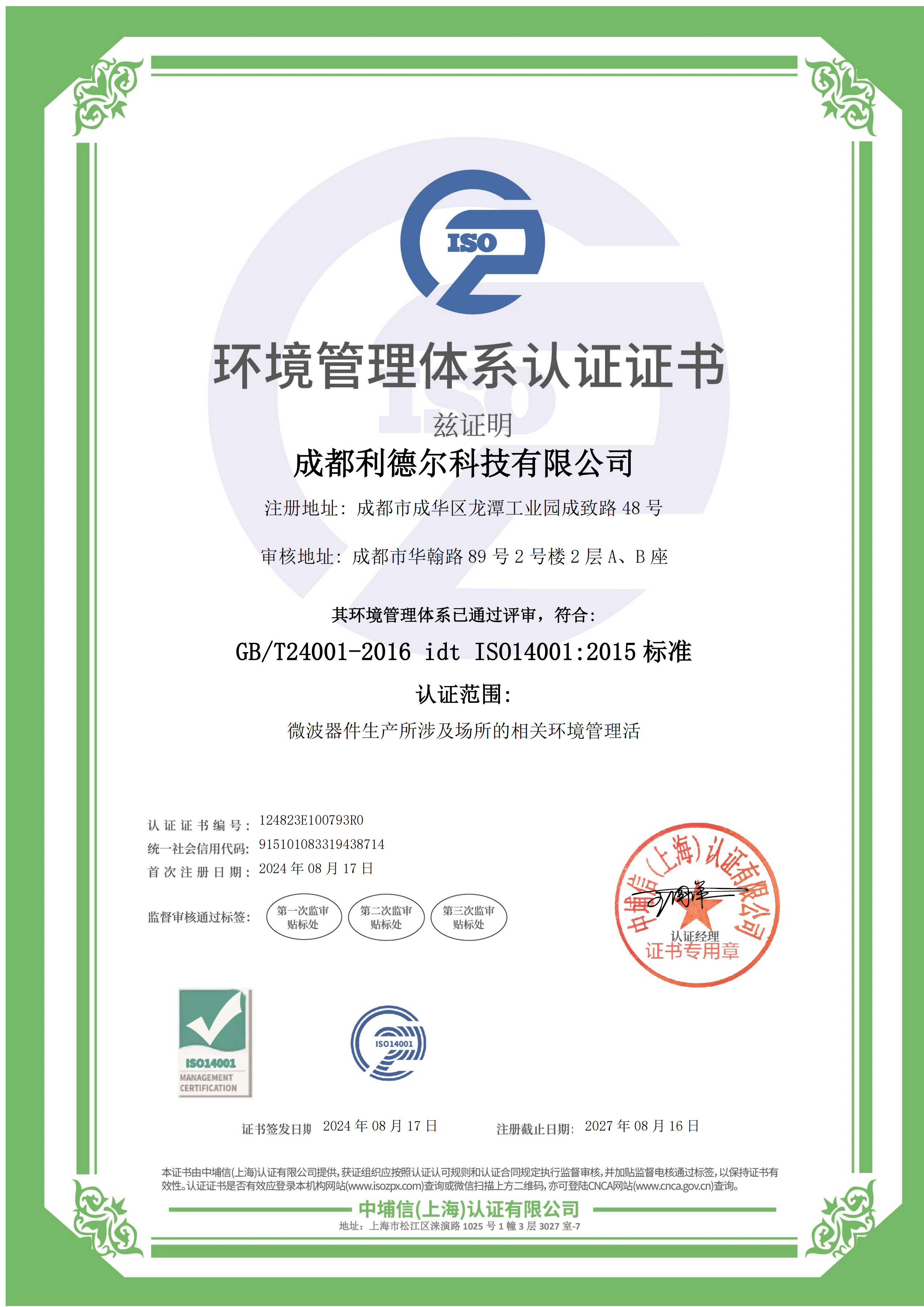
Chengdu Leader Microwave Technology Co.,Ltd. is a leading manufacturer in the RF/Microwave passive components with over 25 years of production experience. We design and manufacture RF/Microwave products in a wide frequency range from DC to 70GHz, including RF power divider/splitter, RF directional coupler, hybrid coupler, duplexer, filter, attenuator, combiner, Antenna, Isolator, circulator, RF/Microwave cable assemblies, microwave and millimeter wave components, widely used for military, 5G, satellite, high speed, aerospace, commercial and telecommunication applications.

Fundamental Technical Criteria for RF Microwave Power Sourcing
Engineers must carefully weigh insertion loss, standing wave ratios, power limits, and packaging constraints before confirming component integration.
Operational Frequency Band
Specifies the usable bandwidth from DC to sub-6GHz, Ku/Ka bands, up to 70GHz mmWave. Ensuring flatness, constant group delay, and passband fidelity across operating ranges prevents signal phase distortion and spectral leakage.
Power Handling (CW & Peak)
Continuous Wave (CW) thermal performance constraints dictate continuous RF microwave power ratings, while peak power thresholds prevent catastrophic dielectric breakdown in pulsed defense radar and high-gain Satcom uplink arrays.
Insertion Loss (IL)
Minimizing dissipative and reflection loss preserves link margin, optimizes overall noise figure (NF) in receiver architectures, and lowers dissipation cooling demands in dense broadband transmitters.
VSWR & Return Loss
A low Voltage Standing Wave Ratio (VSWR ≤ 1.25:1) ensures ideal 50-ohm characteristic matching, mitigating standing waves, inter-stage resonance, and destructive back-reflections into GaN/GaAs power amplifiers.
Port-to-Port Isolation
High port-to-port isolation (>20dB to 35dB) eliminates inter-channel crosstalk, prevents destructive coupling, and allows multi-carrier combining without self-jamming or severe intermodulation distortion.
Packaging Architecture
Form-factor decisions span hermetic Coaxial enclosures (SMA, 2.92mm, 2.4mm), compact Surface Mount (SMT) packaging for high-density PCBs, and rigid Waveguide assemblies for high-power E-band millimeter topologies.
Component Rules: Architectural Trade-Offs
Real-world RF microwave power network deployments require balancing bandwidth, losses, and isolation across varied passive topologies.
✔ Power Dividers: Wilkinson vs Resistive vs Hybrid
Wilkinson Dividers: Feature low insertion loss, equal-phase output splitting, and high inter-port isolation via internal isolation resistors. Perfect for phased-array feeds and balanced signal distribution.
Resistive Splitters: Offer ultra-broadband response from DC up to 70GHz in tiny form factors, but induce higher intrinsic losses (6dB nominal for 2-way) and zero inter-port isolation.
90°/180° Hybrid Couplers: Quadrature/Rat-race hybrids are suited for high-power combining, I/Q modulators, and balanced amplifier stages with excellent VSWR handling.
✔ Directional Couplers: Single, Dual & High Directivity
Directional couplers tap transmission power without interrupting primary signal paths.
Single Couplers: Monitor forward signal paths for power leveling and ALC circuitry.
Dual Directional Couplers: Integrate bidirectional loops allowing forward and reflected power measurements simultaneously, critical for real-time VSWR tracking.
High Directivity Designs: Provide directivity over 20-30dB, preventing forward wave energy from skewing reflected wave readings for accurate impedance tracking.
✔ Filters: Cavity vs LC vs Ceramic Resonators
Cavity Filters: Offer unmatched Q-factors, minimal passband insertion loss, and sharp rejection skirts for multi-carrier base stations, despite larger mechanical dimensions.
LC Lumped Element Filters: Exceptional broad bandwidth capabilities below 3GHz within miniature coaxial and surface-mount architectures; lower power capacity.
Ceramic Filters: Provide balanced size-to-performance ratio for mid-band commercial transceivers, though thermal drift must be assessed over industrial ranges.
✔ Isolators: Protecting Amplifiers from Mismatch
Ferrite-based non-reciprocal RF isolators protect sensitive solid-state power amplifiers (SSPA) and TWTA tubes from high reflected energy caused by antenna disconnection, detuning, or open/short circuit anomalies.
Leader Microwave designs ferrite devices that safely steer return energy into integrated internal dummy loads, preventing intermodulation feedback and thermal failure under full-reflection (infinity VSWR) environments.
Mission-Critical Application Matrix
Match your specific operating platform requirements with verified Leader Microwave component series.
| Application Field | Target Frequency | RF Microwave Power | Critical Parameter | Recommended Topology |
|---|---|---|---|---|
| Phased-Array Radar | 1.0 - 18.0 GHz (X/Ku-Band) | High Peak (500W - 2kW) | Phase/Amplitude Matching <±2° | Wilkinson Stripline Divider |
| Satcom Earth Terminals | 17.7 - 31.0 GHz (Ka-Band) | 100W - 400W CW | Minimal Passband Insertion Loss | Precision Waveguide Coupler |
| 5G / Sub-6 Massive MIMO | 600 MHz - 4.8 GHz | 50W - 160W Average | High Isolation & Low PIM (-160 dBc) | Cavity Filter & Low PIM Combiner |
| Aerospace EW / ECM | DC to 40 GHz / 70 GHz | 20W - 100W CW | Ultra-Broadband Flatness, MIL-STD | Broadband Drop-In Isolator |
| Test & Measurement R&D | DC to 67 GHz / 110 GHz | 2W - 10W Precision | High Directivity & Low Return Loss | Resistive & Dual Directional |
Global Markets & Industrial Footprint
Leader Microwave provides standard catalog models alongside fully customized prototypes built to exact client specifications, serving critical high-frequency sectors worldwide.
| Main Markets | Total Revenue % | Main Products Delivered |
|---|---|---|
| Domestic Market | 50% | Filter / Power divider / duplexer / Antenna |
| North America | 20% | Power divider / directional coupler / hybrid modules |
| Russia | 10% | Combiner / power divider / high rejection filter |
| Western Europe | 8% | Cable assemblies / isolator / attenuator |
| South America | 4% | Power divider / directional coupler |
| Asia | 4% | Isolator, circulator, Cable assemblies |
| Others | 4% | Cable assemblies, Attenuator series |
Why Choose Leader Microwave
We take customer needs as the first priority, as their success is also our success. We believe that excellent quality and service, as well as the most competitive prices, will certainly be able to start our good cooperation. Looking forward to working with you to achieve a win-win situation. Quality, performance and reliability you can count on, from Leader Microwave.
Download Simulation Models & Engineering Files
Accelerate your system architecture cycle with verified Touchstone (.s2p/.s4p) S-parameters and mechanical 3D STEP models ready for immediate EDA integration.